5. Mapping & Navigation
SLAM with slam_toolbox, AMCL, and autonomous navigation with Nav2
Summary
Estimated time to completion: 2 hours
Simulated robot: Turtlebot 3 Burger
What will you learn with this unit?
- Simulating a robot with Gazebo and ROS 2
- Kinematic Models: Moving a robot by publishing on topics
- Creating a map of the simulated environment using 2D-SLAM with slam_toolbox
- Using the Advanced Monte Carlo Localization AMCL and the nav2_map_server
- Overview of autonomous navigation with 2D maps using the Nav2 stack
Robot Simulation with Gazebo
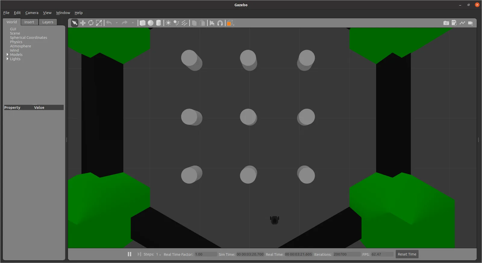
We start by launching the simulation provided by Robotis.
ros2 launch turtlebot3_gazebo turtlebot3_world.launch.pyIn ROS 2 the TurtleBot3 Gazebo launch file already starts robot_state_publisher with the full TF tree, so you do not need a separate bringup.
You should see the following window pop up:
Exercise [5 min]
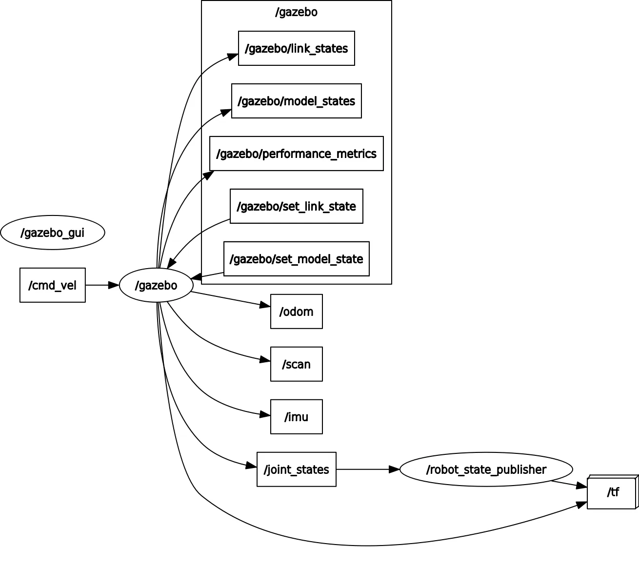
- Inspect the running nodes and topics (
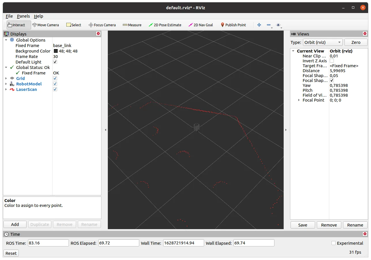
ros2 node list,ros2 topic list) - Visualize the robot model and the laser scan data in RViz2 (
ros2 run rviz2 rviz2)
Moving a Robot by Publishing on a Topic
Mobile Robot Locomotion
We will now briefly discuss mobile robot locomotion and forward kinematics.
The term "robot locomotion" refers to the various strategies that robots use to move from one location to another. In this unit, we focus on wheeled mobile robots. Unlike industrial robots, mobile robots change their pose based on wheel motion. The pose of our robot in the world is thus a function over time and not a function of current angular joint values. The mathematics of forward kinematics (and inverse kinematics, as we will see in the next chapter) is similar to industrial robot kinematics.
The locomotion of mobile robots is based on kinematic assumptions summarized in a "model". In this unit, we analyze and derive kinematic models for mobile robots. Initially, we start considering the most simple mobile robot: a driven wheel.
Consider a simple wheel on a plane. This wheel has a radius r. If the wheel rotates , the distance moved by the center of the wheel is . This can be described by the equation:
Where is the motion of the wheel center.
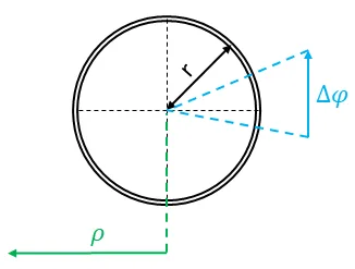
Simple wheel on a plane
However, this mobile robot would be somehow useless because it cannot change the orientation. It can only move along the direction of . Thus, the next step is the extension of this simple wheel model: we add a second wheel and connect the wheels. This model is called a differential-driven mobile robot, and it is the most important model for mobile robotics. A 3D sketch of the model and a 2D simplification is visible in the figure below:
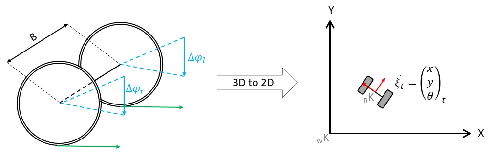
3D model (left) | Simplified 2D model (right)
In the figure on the left side, you see the 3D model. Two wheels are connected with a so-called baseline with length B. Notice that robots, like the one above, are differential mobile robots. This is only true if they have two differently controlled wheels that are in alignment. Based on the wheel movement and , the mobile device is now able to move on a plane. Since the third dimension is not used, a mobile robot is typically controlled on a 2D plane (the top view, see the right part of the figure above).
In the two-dimensional space, the mobile robot is controlled in a world coordinate system/frame .
The pose
at time t is defined in the world frame. However, the wheel motion is described in the wheel coordinate system and can be projected into the robot coordinate system _RK (see red coordinate system) using the kinematic configuration.
Now, it should be obvious that the pose at t must be somehow a function of the wheel motion and the previous pose . In this section, we will derive functions mapping motion from the world coordinate system to the wheel coordinate system and vice versa.
Deriving the Change of Pose
In this unit, we will only work with differential drive or holonomic mobile robots. Let us continue with the derivation of the change of pose to . Consider the following image.
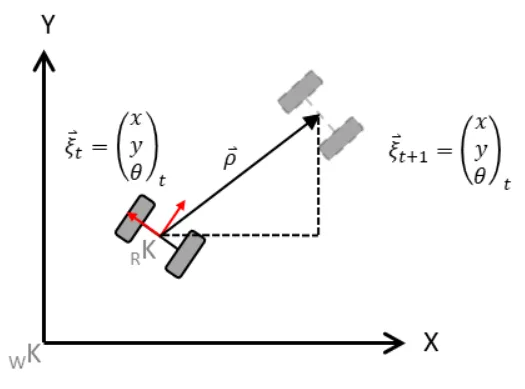
Simplified Kinematic Model of the Mobile Robot
Thus we define the robot state and want to calculate the new state based on the motion of the left wheel and the right wheel .
As we can see, the robot will move meters. The X- and Y-components of have to be estimated based on the latest orientation of the robot (e.g. ) and the change of orientation. This change of the robot's orientation, as well as , are functions of the wheel motion.
The driven distance:
The change in orientation:
(Where B is the baseline — the distance between the wheels). Based on these calculations, the movement of the robot can be determined. For this calculation, we must know the previous pose . Accumulating the robot's motion leads to the new pose. To calculate this, we "split" the motion into the X and Y components.
This is simply done by using sine and cosine:
However, the equation has a shortcoming: it assumes a linear movement of the robot, but it is sufficient for our purposes. A more exact solution will be discussed in a different unit.
Forward Kinematics in ROS 2
Now that we know how to calculate the forward kinematics of a differential drive mobile robot, let's see how we implement it using ROS 2. (Remember that we already moved the TurtleBot in the previous unit in the move_turtlebot.py file).
In the following example, we will create a node that moves the robot to a specific pose referenced to the starting pose of the robot:
Simple Goal Mover in ROS 2
In this example, we'll implement a simple goal mover using ROS 2. The robot will move to a specified position in a simulated Gazebo environment.
import math
import rclpy
from rclpy.node import Node
from rclpy.qos import QoSPresetProfiles

from geometry_msgs.msg import Point, Twist
from nav_msgs.msg import Odometry


def euler_from_quaternion(x, y, z, w):
    # yaw (z-axis rotation) — everything we need for a planar robot
    siny_cosp = 2.0 * (w * z + x * y)
    cosy_cosp = 1.0 - 2.0 * (y * y + z * z)
    return math.atan2(siny_cosp, cosy_cosp)


class SimplePose(Node):
    def __init__(self):
        super().__init__('simple_pose')
        self.x = 0.0
        self.y = 0.0
        self.theta = 0.0
        self.goal_tolerance = 0.2

        # Sensor-style streams are usually best-effort
        self.sub = self.create_subscription(
            Odometry, '/odom', self.odom_callback,
            QoSPresetProfiles.SENSOR_DATA.value,
        )
        self.pub = self.create_publisher(Twist, '/cmd_vel', 1)

    def odom_callback(self, msg):
        """Update the robot's pose from odometry."""
        self.x = msg.pose.pose.position.x
        self.y = msg.pose.pose.position.y
        q = msg.pose.pose.orientation
        self.theta = euler_from_quaternion(q.x, q.y, q.z, q.w)

    def go_to(self, goal: Point):
        """Simple state machine: rotate toward the goal, then drive."""
        speed = Twist()
        rho = float('inf')
        while rclpy.ok() and rho > self.goal_tolerance:
            rclpy.spin_once(self, timeout_sec=0.1)
            delta_x = goal.x - self.x
            delta_y = goal.y - self.y
            rho = math.hypot(delta_x, delta_y)
            self.get_logger().info(f'Distance to goal= {rho:.2f}m', throttle_duration_sec=1.0)
            angle_to_goal = math.atan2(delta_y, delta_x)

            if abs(angle_to_goal - self.theta) > 0.1:
                speed.linear.x = 0.0
                speed.angular.z = 0.3
            else:
                speed.linear.x = 0.22
                speed.angular.z = 0.0
            self.pub.publish(speed)

    def stop_robot(self):
        self.pub.publish(Twist())


def main(args=None):
    rclpy.init(args=args)
    node = SimplePose()

    # Wait until /odom has delivered at least one message
    self = node  # readability
    self.get_logger().info('Waiting for /odom …')
    while rclpy.ok() and self.x == 0.0 and self.y == 0.0:
        rclpy.spin_once(self, timeout_sec=0.5)

    goal = Point(x=5.0, y=5.0, z=0.0)
    try:
        node.go_to(goal)
    except KeyboardInterrupt:
        pass
    finally:
        node.stop_robot()
        err = math.hypot(goal.x - node.x, goal.y - node.y)
        node.get_logger().info(f'Final position error: {err:.2f}m')
        node.destroy_node()
        rclpy.shutdown()


if __name__ == '__main__':
    main()
Explanation
- Class Initialization: We define the
SimplePoseclass, which creates a subscriber on/odomand a publisher on/cmd_vel. - Odometry Callback: This method updates the robot's current position (
x,y, andtheta) using the odometry data. - Move to Goal: In the
go_tomethod, we calculate the distance (rho) and angle to the goal. If the robot is not facing the correct direction, it will rotate until aligned, then move straight.rclpy.spin_once()inside the loop lets us keep processing odometry messages while we drive. - Stopping the Robot: After reaching the goal, the robot stops.
Exercise [10 min]
Create a launch file with the name simulation2.launch.py that:
- Spawns the TurtleBot3 Burger in an empty Gazebo world at position x=0, y=0
- Starts the just now created
simple_posenode and try to understand the code - Comment the functions in the
simple_posecode so that you understand what is happening
Exercise Solution
Mapping
Mapping describes the process of generating a usable map. In ROS 2 this map is described using two files:
- An image: The discretized map is described using pixels. A white pixel is free, a gray is unknown and a black is occupied
- A yaml description file: This file describes the map's hyperparameters such as square meters per pixel
In this unit, we use the slam_toolbox SLAM package — it replaces gmapping from ROS 1 and is the default 2D SLAM solution in ROS 2.
slam_toolbox subscribes to the laser scan topic and to the odom→base_link TF; it publishes the /map and the map→odom TF. The default hyperparameters of the algorithm are typically good enough for our purpose. Initially, the map will look like the following sketch:
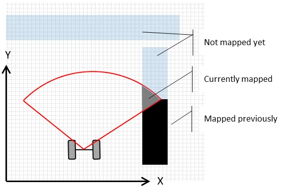
The map will be created during manual robot movement (though autonomous solutions like frontier exploration also exist). Depending on your system, a ROS 2 teleop_keyboard is enough for this task.
Additional Information
As mentioned previously, modern mobile robotics heavily relies on statistics. The slam_toolbox package is a SLAM (Simultaneous Localization and Mapping) application. In SLAM, we estimate both the current robot pose and the map . This estimation is based on the knowledge gathered so far — movement commands and measurements . This is summarized by the probability distribution:
slam_toolbox Demo
We will use the existing TurtleBot3 simulation in Gazebo provided by ROBOTIS. Execute the following commands in separate terminals:
Install the required packages (one-time setup inside the container):
sudo apt update && sudo apt install -y \
  ros-humble-nav2-bringup \
  ros-humble-slam-toolbox \
  ros-humble-turtlebot3-gazebo \
  ros-humble-turtlebot3-navigation2

echo 'export TURTLEBOT3_MODEL=burger' >> ~/.bashrc
source ~/.bashrc
Start the simulation in Gazebo and spawn the robot in the world:
ros2 launch turtlebot3_gazebo turtlebot3_world.launch.pyStarts the slam_toolbox SLAM for the TurtleBot3. We launch it in online async mode, which is the default for real-time mapping. The use_sim_time:=true flag is critical when running against a simulator — it tells the node to use /clock instead of wall time.
ros2 launch slam_toolbox online_async_launch.py use_sim_time:=trueOpen RViz2 with the navigation view (it already subscribes to /map, /scan, and the robot model):
ros2 launch nav2_bringup rviz_launch.pyNow drive the robot around to create the map. To enable teleoperation, you can run the following command:
ros2 run turtlebot3_teleop teleop_keyboardAlternatively, you could use rqt_robot_steering for control.
ros2 run rqt_robot_steering rqt_robot_steeringLet's save our map in a folder named maps inside our package first_pkg with the name my_map. Make a folder called maps in the first_pkg package share dir:
mkdir -p ~/ros2_ws/src/first_pkg/mapsMove to the home directory:
cd Save the map using the Nav2 map saver CLI:
ros2 run nav2_map_server map_saver_cli -f ~/ros2_ws/src/first_pkg/maps/my_mapThis writes my_map.pgm (the occupancy image) and my_map.yaml (metadata).
Exercise [5 min]
- Move the robot using any teleoperation method we've discussed so far.
- Inspect the TF tree (
ros2 run tf2_tools view_frames) and rqt_graph. What do you observe? - Create a complete map of the environment.
- Open RViz2 and visualize the following:
- Robot model
- TFs (without names)
- Laser scan data
- The map created by slam_toolbox
Refer to the following figures for the desired output in RViz2.
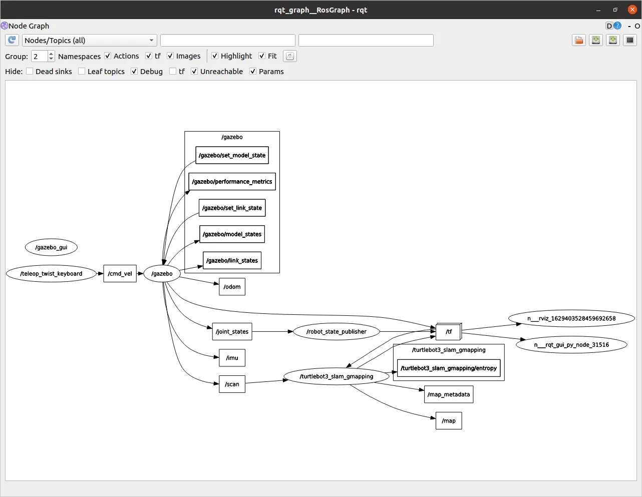
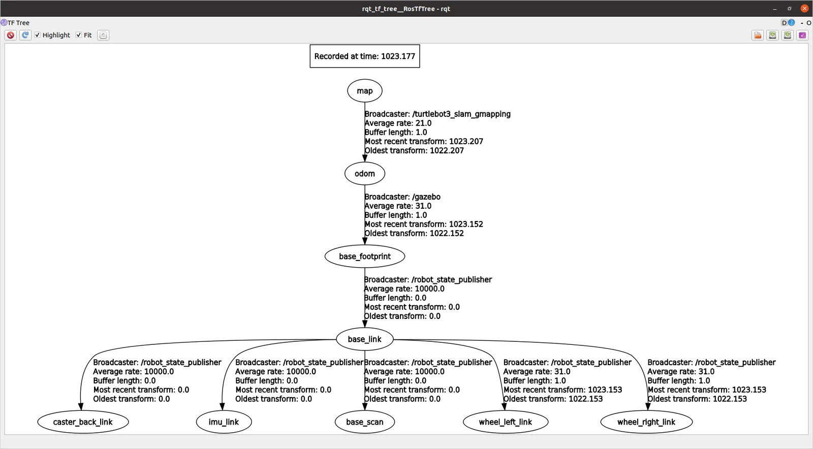
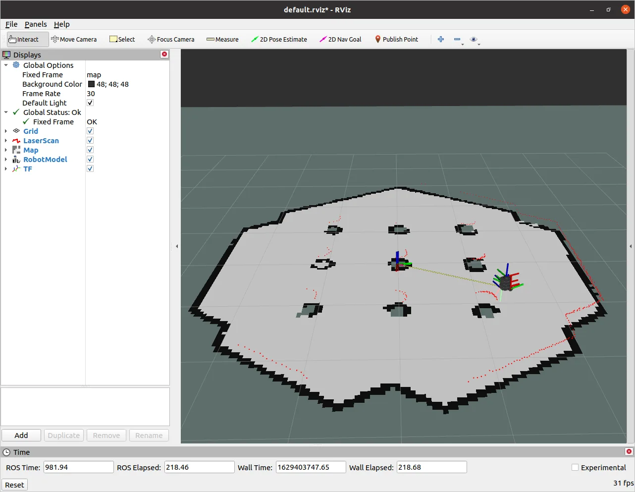
Now that we know how to create a map, let's look into how to save it for later.
Map Server
The nav2_map_server provides utilities to create the YAML and image file.
The syntax is:
ros2 run nav2_map_server map_saver_cli -f <mapname> --ros-args -p save_map_timeout:=10000Exercise [1 min]
- Inspect the generated YAML file.
Exercise Solution
Localization
Localization Using AMCL
You have already learned the principles of mobile robot localization using wheel motion and kinematics. We have also discussed the issue of noisy data, but we have not found a full solution for the process and sensor noise. Without delving into deeper topics (which are part of the master degree program "Master in Robot Engineering"), we can formulate the main problem: it is not possible to describe robot motion and the robot's state using classic statistical models, such as multivariate Gaussian distributions.
Instead of using parametric probability density functions to describe the robot's state and motion, we can use a technique from statistical physics called Markov Chain Monte Carlo (MCMC). MCMC uses many (typically more than 500) samples or potential hypotheses of the robot's state, referred to as "particles". This approach is known as a particle filter. The method can be simplified into two main steps:
-
Sampling: Each particle is moved according to a noisy motion command. For example, using noisy motion data, we estimate each particle's movement using kinematics. Each particle moves in accordance with the real physical movement. Next, we evaluate each particle using sensor signals (e.g., checking if the motion is consistent with sensor values, like those from an accelerometer) in a probabilistic framework. This results in a set of moved particles, each weighted by the sensor data.
-
Resampling: Imagine you have a bag of colored balls — two red and eight blue. The probability of drawing a red ball is 20%. If you sample "with replacement" (putting the ball back after each draw), you should draw a red ball 20% of the time. In resampling, particles are selected based on their weight (better particles are sampled more often). This creates a "survival of the fittest" scenario, where the best hypothesis of the robot's state survives.
The following figure illustrates a particle filter application for robot localization. Each arrow represents a particle, with the starting point representing the robot's position and the arrow's direction indicating orientation (length is not significant).
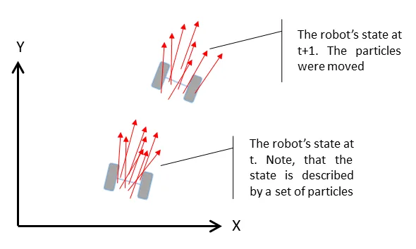
Sketch of Particle Filter in ROS 2
The particle filter is implemented in the nav2_amcl package — the direct successor of the ROS 1 amcl node, now a lifecycle node managed by Nav2. As shown in the figure above, particles spread further from the "ground truth" over time. To correct this, global information (e.g., maps) is used.
References:
- C.M. Bishop; Pattern Recognition and Machine Learning; Springer, 2006
- S. Thrun, W. Burgard & D. Fox; Probabilistic Robotics (Intelligent Robotics and Autonomous Agents series); The MIT Press, 2005
AMCL + Nav2 Demo
We will now use the Nav2 stack (which includes AMCL) with the map we created. Start everything except for the mapping:
Starts simulation in Gazebo with the robot inside:
ros2 launch turtlebot3_gazebo turtlebot3_world.launch.pyStart the full Nav2 bringup with our saved map. This launches amcl, the map_server, the planner_server, the controller_server, the bt_navigator, the behavior_server and the lifecycle_manager that brings them all up in order:
ros2 launch nav2_bringup bringup_launch.py \
  use_sim_time:=true \
  map:=$HOME/ros2_ws/src/first_pkg/maps/my_map.yaml
Wait until you see:
[lifecycle_manager-XX] [INFO] [lifecycle_manager_navigation]: Managed nodes are activeThat's your signal that all the lifecycle servers are configured and active.
Also open RViz2 with the Nav2 configuration:
ros2 launch nav2_bringup rviz_launch.py use_sim_time:=trueAt the beginning the robot doesn't know where it is. You can help the robot by setting an initial pose estimate in RViz2. This is done by clicking the "2D Pose Estimate" button and dragging the arrow where the robot actually is.

Now the robot will localize itself. Now let the robot do the work for you. You can use the "Nav2 Goal" button in RViz2 to set a goal for the robot. The robot will move to the goal and localize itself better with each resampling step.

Nav2 / AMCL Launch File
The Nav2 demo above was very TurtleBot specific because it uses the default nav2_params.yaml. However you can configure everything by yourself:
Make an rviz folder in the first_pkg package:
mkdir -p ~/ros2_ws/src/first_pkg/rvizCreate a new file called rviz_config.rviz in the rviz folder:
touch ~/ros2_ws/src/first_pkg/rviz/rviz_config.rvizIn RViz2, display the following:
- Robot Model
- Laser Scan
- TFs (without names)
- Map
- PoseArray (
/particle_cloud)
Make a new launch file called amcl.launch.py in the first_pkg package:
touch ~/ros2_ws/src/first_pkg/launch/amcl.launch.pyPaste the following code into the launch file:
import os
from ament_index_python.packages import get_package_share_directory
from launch import LaunchDescription
from launch.actions import IncludeLaunchDescription, DeclareLaunchArgument
from launch.launch_description_sources import PythonLaunchDescriptionSource
from launch.substitutions import LaunchConfiguration
from launch_ros.actions import Node


def generate_launch_description():
    pkg_share = get_package_share_directory('first_pkg')
    tb3_gazebo = get_package_share_directory('turtlebot3_gazebo')
    nav2_bringup = get_package_share_directory('nav2_bringup')

    map_file = LaunchConfiguration('map')
    rviz_cfg = os.path.join(pkg_share, 'rviz', 'rviz_config.rviz')

    return LaunchDescription([
        DeclareLaunchArgument(
            'map',
            default_value=os.path.join(pkg_share, 'maps', 'my_map.yaml'),
            description='Full path to the map YAML file'),

        # Start the TurtleBot3 world
        IncludeLaunchDescription(
            PythonLaunchDescriptionSource(
                os.path.join(tb3_gazebo, 'launch', 'turtlebot3_world.launch.py'))),

        # Start full Nav2 bringup (map_server, amcl, planner, controller, bt_navigator, …)
        IncludeLaunchDescription(
            PythonLaunchDescriptionSource(
                os.path.join(nav2_bringup, 'launch', 'bringup_launch.py')),
            launch_arguments={
                'use_sim_time': 'true',
                'map': map_file,
            }.items()),

        # RViz2 with our saved config
        Node(
            package='rviz2',
            executable='rviz2',
            arguments=['-d', rviz_cfg],
            output='screen',
        ),
    ])
Don't forget to tell ament_python to install the launch, maps, and rviz folders. In setup.py:
import os
from glob import glob

data_files=[
    ('share/ament_index/resource_index/packages',
        ['resource/' + package_name]),
    ('share/' + package_name, ['package.xml']),
    (os.path.join('share', package_name, 'launch'), glob('launch/*launch.py')),
    (os.path.join('share', package_name, 'maps'),   glob('maps/*')),
    (os.path.join('share', package_name, 'rviz'),   glob('rviz/*')),
],
Rebuild and source:
cd ~/ros2_ws && colcon build --packages-select first_pkg --symlink-install && source install/setup.bashNow launch the file:
ros2 launch first_pkg amcl.launch.pyIf you choose Fixed Frame: base_footprint in RViz2, you will see the robot's pose.
You may have noticed that the map is somewhere else.
That's because the robot doesn't know where it is and there is No transform from [map] to [base_footprint].
You could calculate that with a fixed transformation, but there is a better way. We are already using the AMCL algorithm inside the Nav2 bringup to localize the robot — you just need to provide the initial pose via the "2D Pose Estimate" tool.
Tuning AMCL parameters
If you want to override the default AMCL parameters (for instance to match the TurtleBot3's laser range or to change particle counts), create a nav2_params.yaml copy and pass it to bringup_launch.py as params_file:=…. The relevant block looks like this:
amcl:
  ros__parameters:
    use_sim_time: true
    min_particles: 200
    max_particles: 1000
    kld_err: 0.02
    update_min_d: 0.20
    update_min_a: 0.20
    resample_interval: 1
    transform_tolerance: 0.5
    recovery_alpha_slow: 0.00
    recovery_alpha_fast: 0.00
    initial_pose:
      x: -1.5
      y: 0.5
      yaw: 0.0
    laser_max_range: 3.5
    laser_max_beams: 180
    z_hit: 0.5
    z_short: 0.05
    z_max: 0.05
    z_rand: 0.5
    sigma_hit: 0.2
    lambda_short: 0.1
    laser_likelihood_max_dist: 2.0
    laser_model_type: likelihood_field
    robot_model_type: nav2_amcl::DifferentialMotionModel
    alpha1: 0.1
    alpha2: 0.1
    alpha3: 0.1
    alpha4: 0.1
    odom_frame_id: odom
    base_frame_id: base_footprint
    scan_topic: scan
Launch it with:
ros2 launch nav2_bringup bringup_launch.py \
  use_sim_time:=true \
  map:=$HOME/ros2_ws/src/first_pkg/maps/my_map.yaml \
  params_file:=$HOME/ros2_ws/src/first_pkg/config/nav2_params.yaml
Now let the robot drive to a goal. The robot will move to the goal and localize itself better with each resampling step.
Exercise Solution
Sending goals from code
You don't have to use RViz2 — you can send navigation goals from any node via the NavigateToPose action.
From the command line
ros2 action send_goal /navigate_to_pose nav2_msgs/action/NavigateToPose \
"{pose: {header: {frame_id: 'map'}, pose: {position: {x: 1.5, y: 0.5}, orientation: {w: 1.0}}}}" \
--feedback
From Python
import rclpy
from rclpy.action import ActionClient
from rclpy.node import Node
from nav2_msgs.action import NavigateToPose
from geometry_msgs.msg import PoseStamped


class GoalSender(Node):
    def __init__(self):
        super().__init__('goal_sender')
        self._client = ActionClient(self, NavigateToPose, 'navigate_to_pose')

    def send_goal(self, x: float, y: float):
        self._client.wait_for_server()

        goal = NavigateToPose.Goal()
        goal.pose = PoseStamped()
        goal.pose.header.frame_id = 'map'
        goal.pose.header.stamp = self.get_clock().now().to_msg()
        goal.pose.pose.position.x = x
        goal.pose.pose.position.y = y
        goal.pose.pose.orientation.w = 1.0

        future = self._client.send_goal_async(goal, feedback_callback=self.on_feedback)
        future.add_done_callback(self.on_response)

    def on_feedback(self, msg):
        self.get_logger().info(
            f'distance remaining: {msg.feedback.distance_remaining:.2f} m')

    def on_response(self, future):
        handle = future.result()
        if not handle.accepted:
            self.get_logger().error('Goal rejected')
            return
        handle.get_result_async().add_done_callback(self.on_result)

    def on_result(self, future):
        self.get_logger().info(f'Result: {future.result().result}')
        rclpy.shutdown()


def main(args=None):
    rclpy.init(args=args)
    node = GoalSender()
    node.send_goal(1.5, 0.5)
    rclpy.spin(node)


if __name__ == '__main__':
main()Homework [10 Points]
Create a launch file unit3_hw.launch.py inside the first_pkg that:
- Spawns the TurtleBot3 Burger in an empty world.
- Starts the Python file
unit3_hw.py.
Create a Python file unit3_hw.py inside first_pkg that:
- Makes the robot drive to goal points via the
NavigateToPoseaction, each containing the coordinates , where . - Ensures that the robot stops at the final goal point.
Ordinary Wizarding Level
7 questions · 5 pts first try · 2 pts on a later try · +15 bonus for a clean sweep
Question 1 of 7